Assembly Guide
This guide describes how to assemble PrintExo from 3D-printed components, off-the-shelf mechanical parts, and electronics.
1. Overview
PrintExo uses a modular architecture organized into three main subsystems:
| Subsystem | Description |
|---|---|
| Actuation module | Motor, planetary gear stage, protective casing |
| Shank structure | Vertical frame, passive hinge, calf attachment |
| Shoe interface | Dorsal component, plantar guides, lace integration |
Assembly follows a bottom-up approach: gearbox → actuation module → shank → shoe interface.
2. Before You Begin
Checklist
- [ ] All 3D-printed parts completed and post-processed
- [ ] All BOM components available (bearings, fasteners, motor)
- [ ] Required tools prepared
- [ ] Clean, well-lit workspace
Recommended Preparation
- Verify printed parts — check for warping, incomplete features, or layer defects
- Ream all holes — use appropriate drill bits to clean up M3 holes
- Tap threads — tap M3 holes where bolts will be inserted
- Dry-fit bearings — ensure press-fit is snug but not cracked
3. Required Tools
| Tool | Size/Spec | Purpose |
|---|---|---|
| Hex key set | 2.5 mm (for M3) | Tightening bolts |
| Screwdriver | Phillips / Flat | General fastening |
| Drill bits | 2.5 mm, 3.0 mm | Hole reaming |
| Hand tap | M3 × 0.5 | Threading holes |
| Needle-nose pliers | — | Support removal, small parts |
| Calipers | — | Dimensional verification |
| Power drill (optional) | — | Speeds up drilling/tapping |
4. Assembly Steps
Step 1 — Sun Gear Assembly
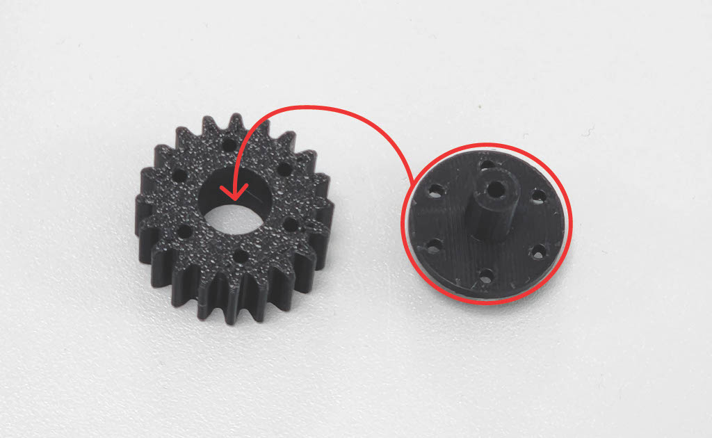
Fit the Sun Gear to the Sun Gear Holder.
Step 2 — Align Screw Holes
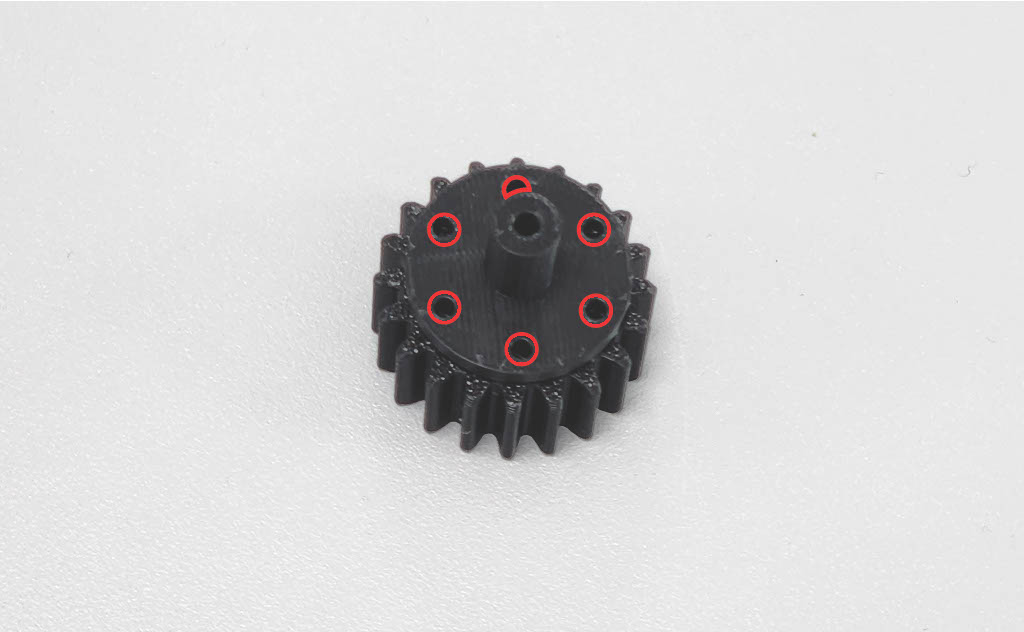
Align the screw holes.
Step 3 — Fasten Sun Gear
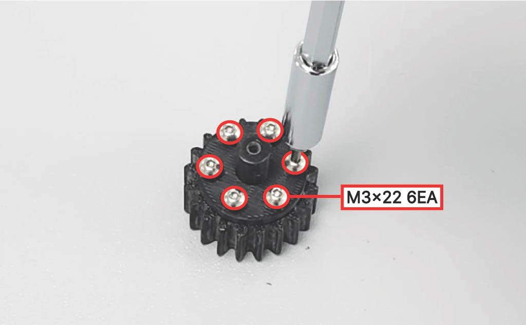
Fasten using six (6) M3 × 22 mm screws until each screw contacts the bottom surface.
Step 4 — Mount Sun Gear to Actuation Module
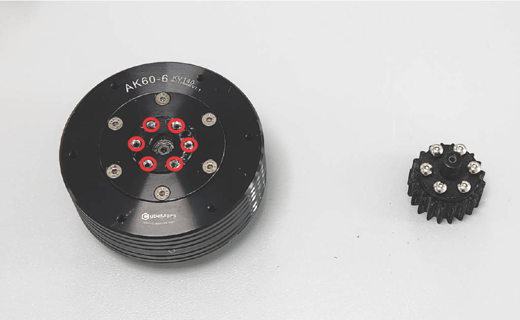
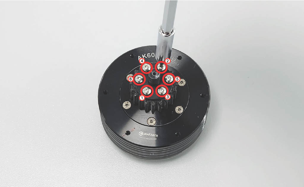
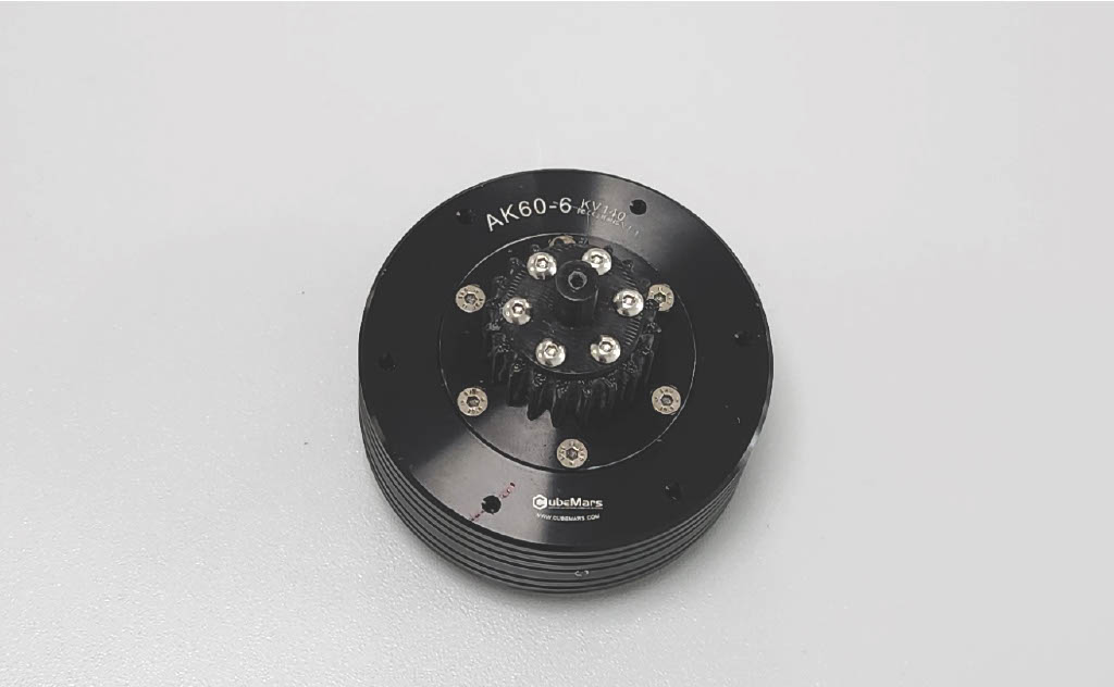
Align the Sun Gear with the six (6) screw holes on the Actuation Module (CubeMars AK60-6 V1.1 KV140). Fasten in the specified order, then tighten fully.
⚠️ Caution: Do not let any screw tilt the Sun Gear contact surface.
Step 5 — Planet Gear Bearing Installation
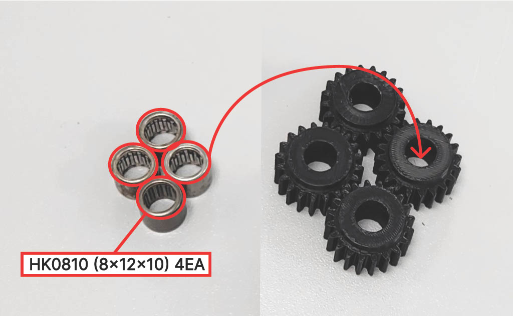
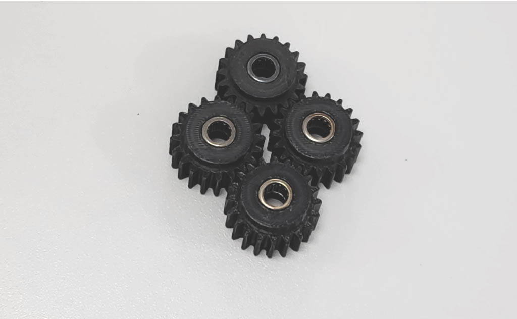
Insert one (1) HK0810 (8×12×10) into each of the four (4) Planet Gears.
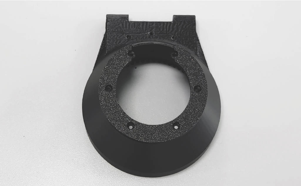
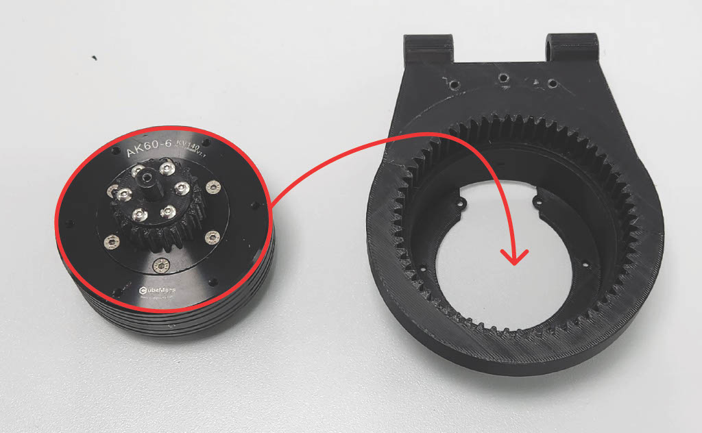
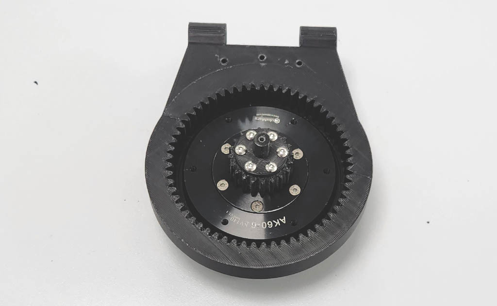
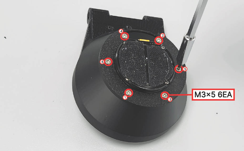
Step 6 — Ring Gear Installation
Align the Ring Gear with the Actuation Module, then insert it fully.
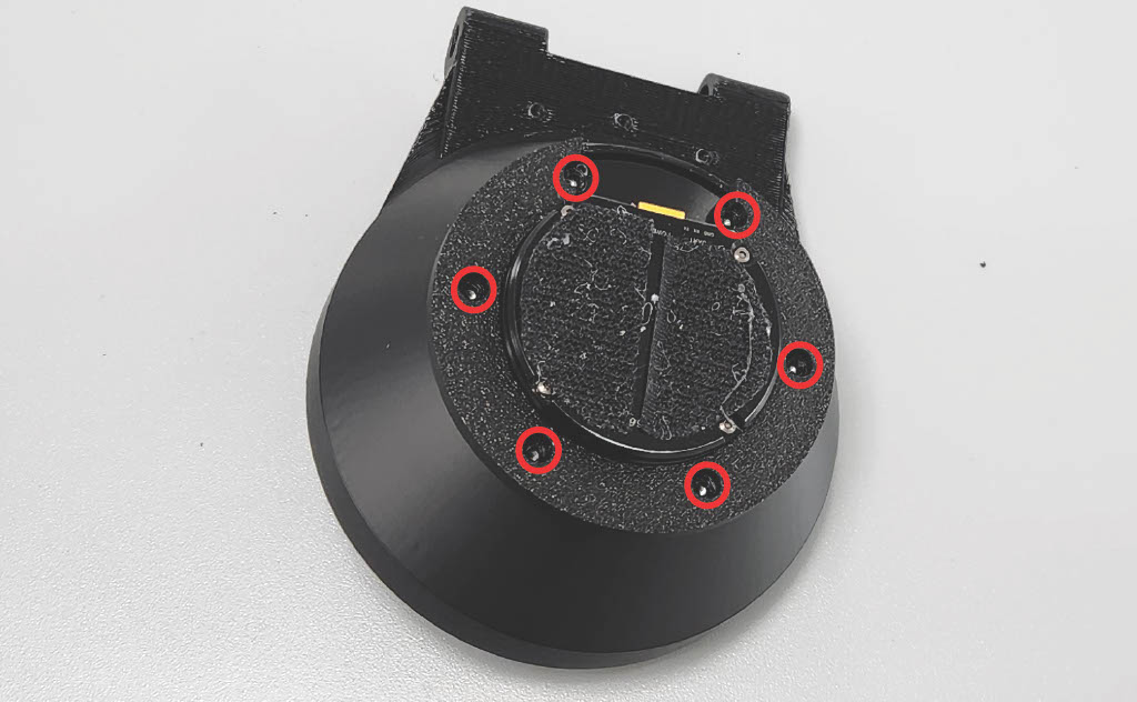
Step 7 — Secure Ring Gear
Fasten using six (6) M3 × 5 mm screws in the specified order, then tighten fully.
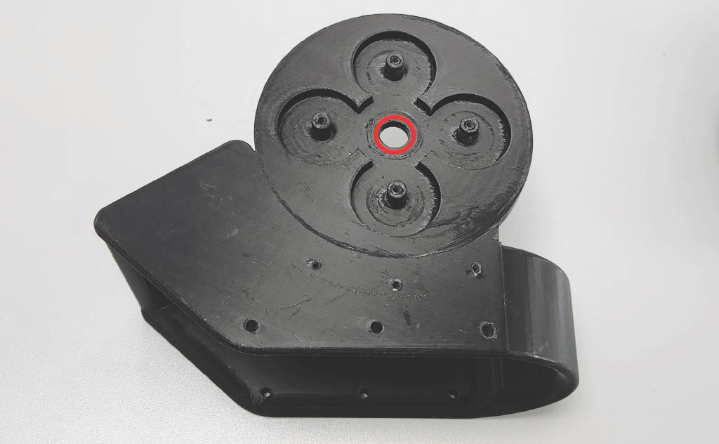
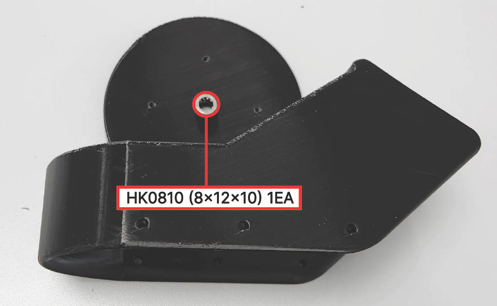
Step 8 — Carrier Bearing Installation
Insert one (1) HK0810 (8×12×10) into the Carrier.
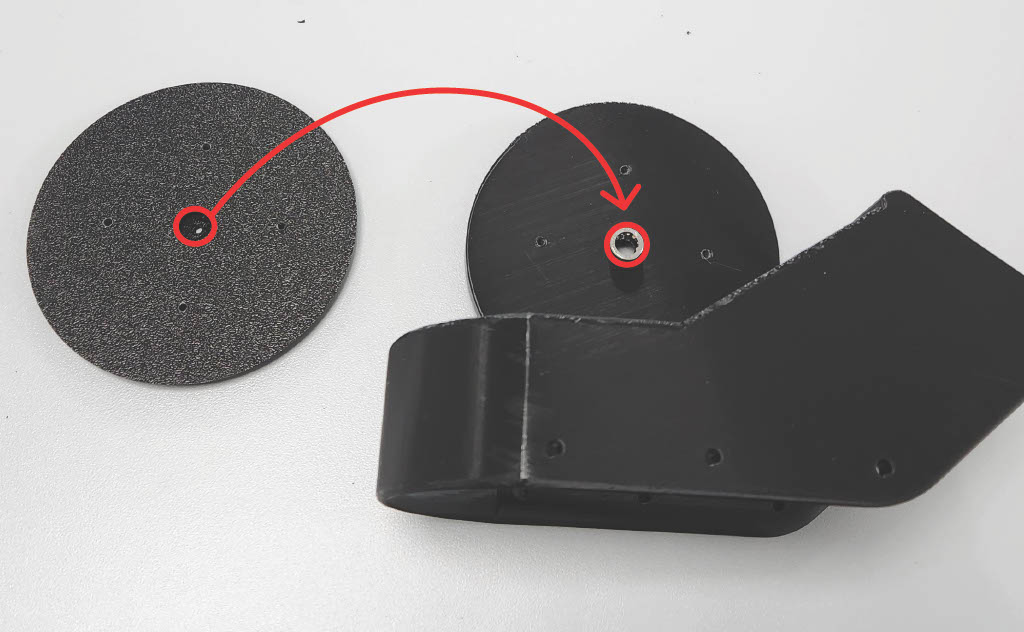
Step 9 — Medial Gearbox Bracket
Align the Medial Gearbox Bracket with the bearing, then insert it fully.
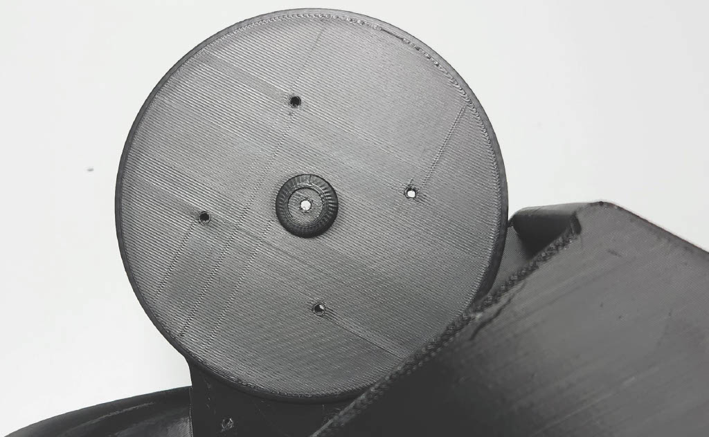
Step 10 — Planet Gears Installation
Align the four (4) Planet Gears with the bearings, then insert them fully.
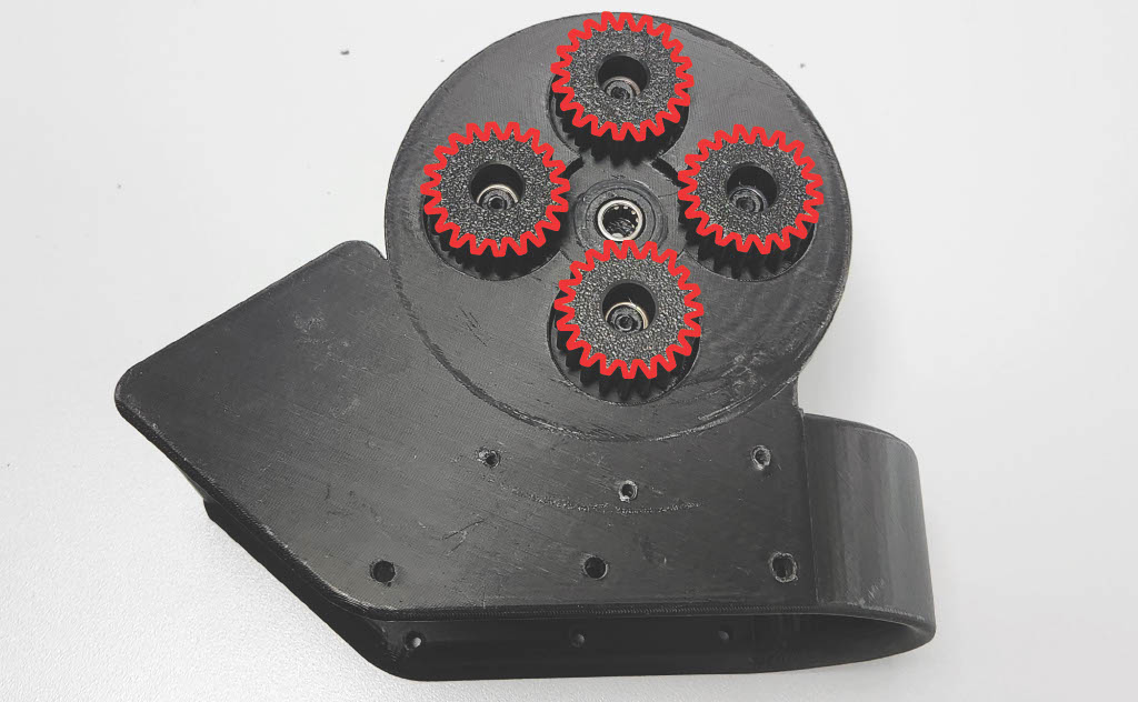
Step 11 — Sun Gear Engagement
Align the Actuation Module Sun Gear with the bearing, then insert it fully.
⚠️ Caution: Align the teeth of the four (4) Planet Gears with the teeth of the Sun Gear.
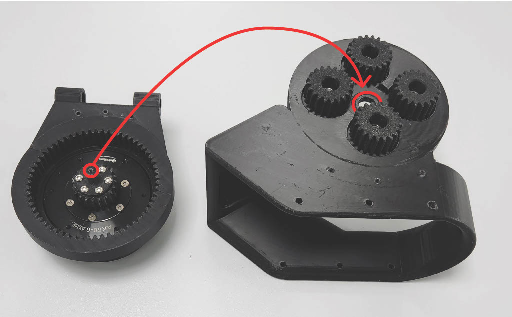
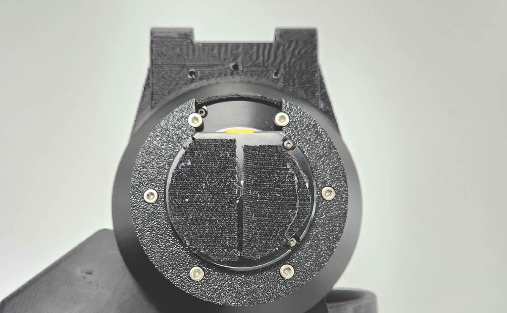
Step 12 — Carrier Fastening
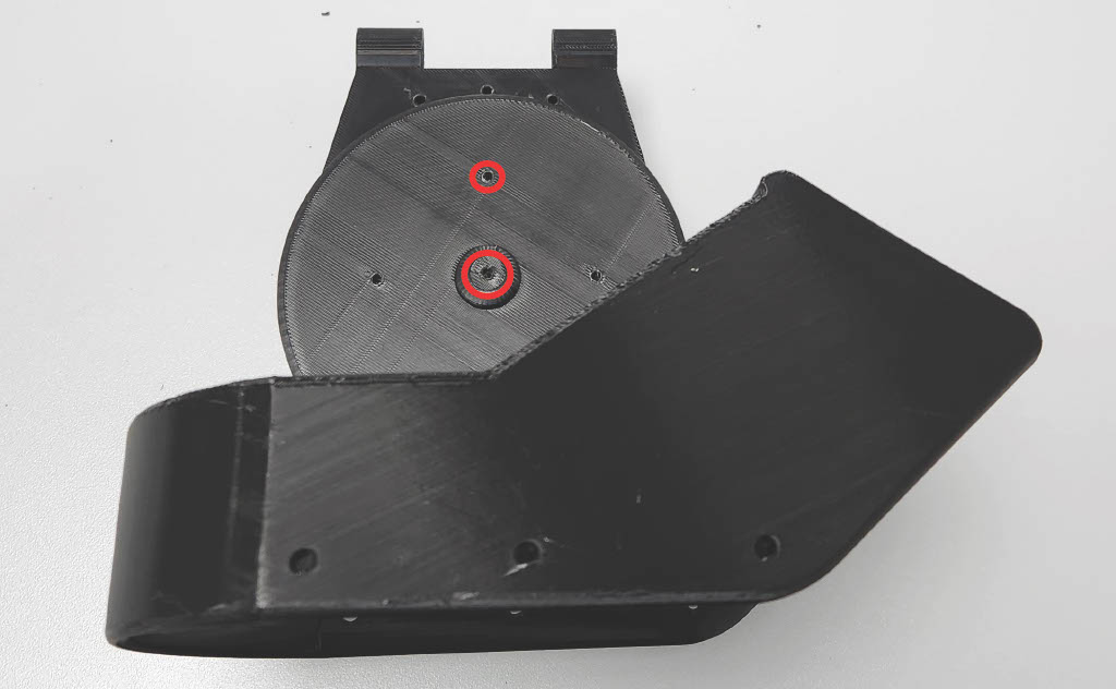
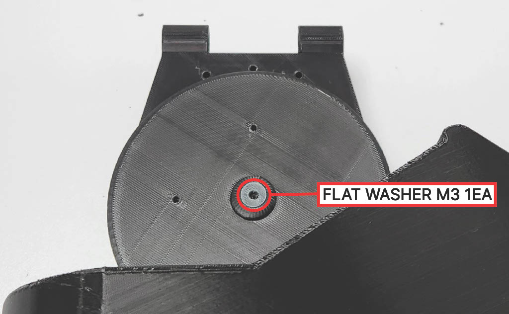
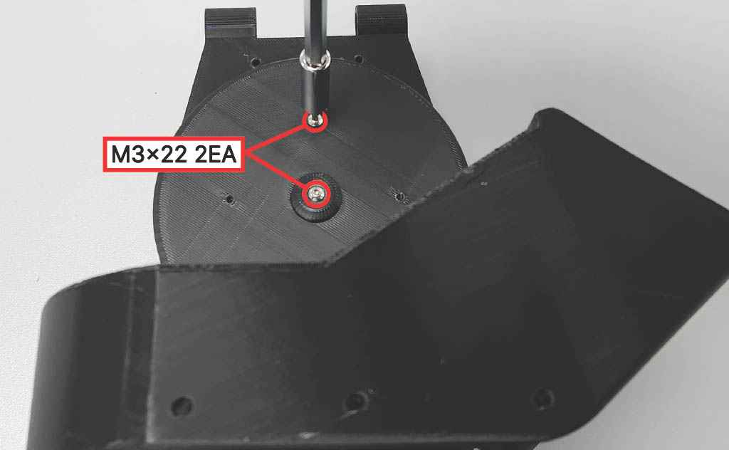
Insert M3 flat washers, then fasten the Carrier to the Actuation Module using two (2) M3 × 22 mm screws. Tighten fully.
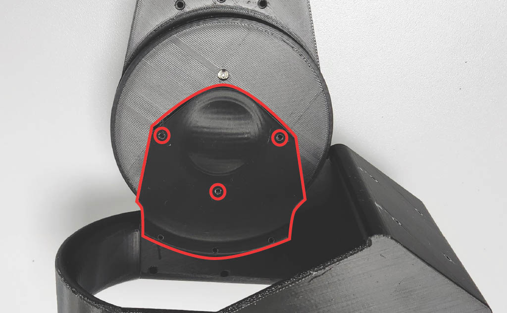
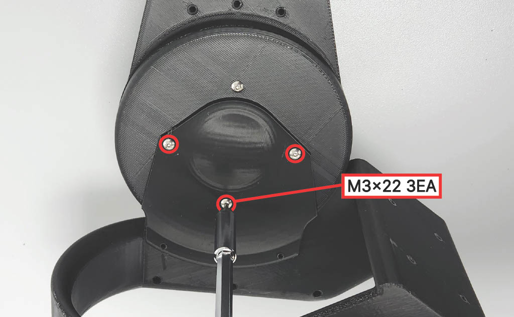
Step 13 — Medial Cover
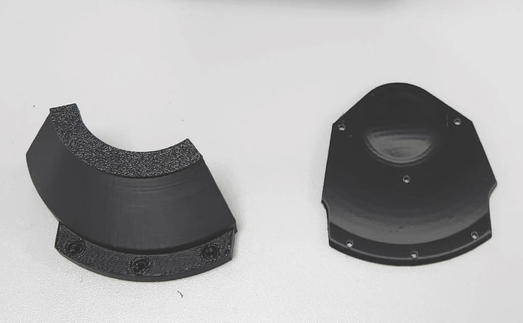
Fasten the Medial Cover using three (3) M3 × 22 mm screws. Tighten fully.
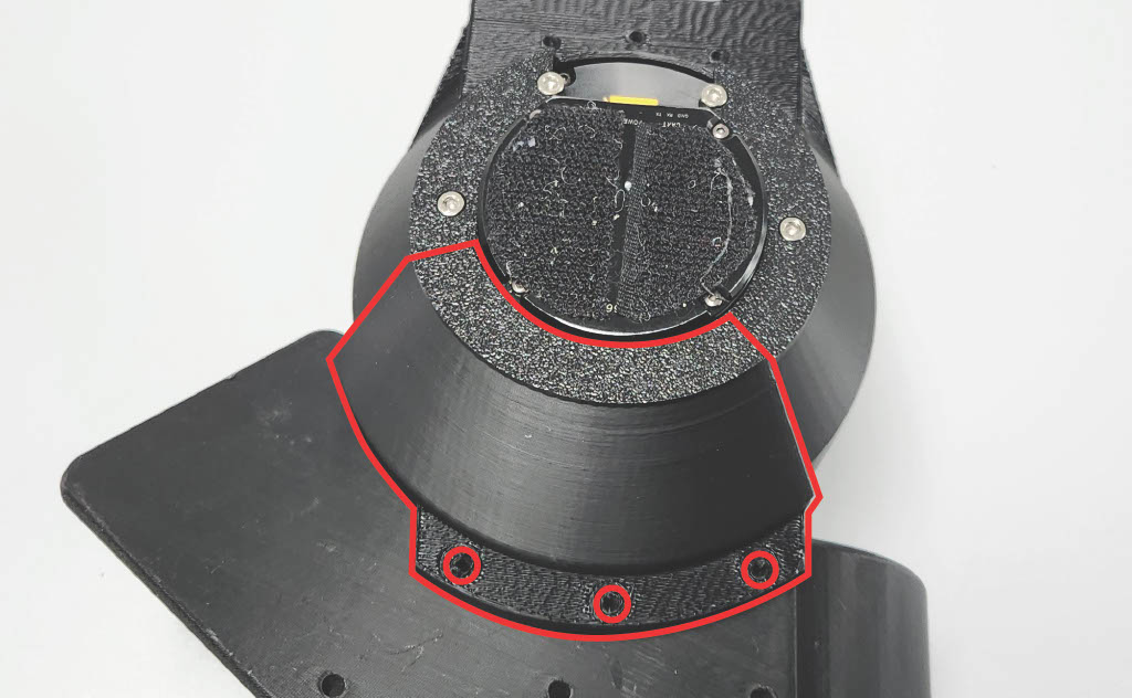
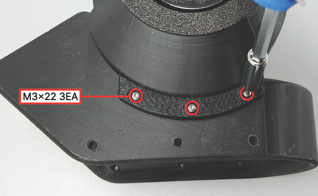
Step 14 — Lower Bracket
Fasten the Lower Bracket using three (3) M3 × 22 mm screws. Tighten fully.
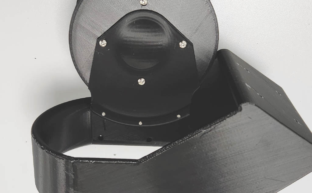
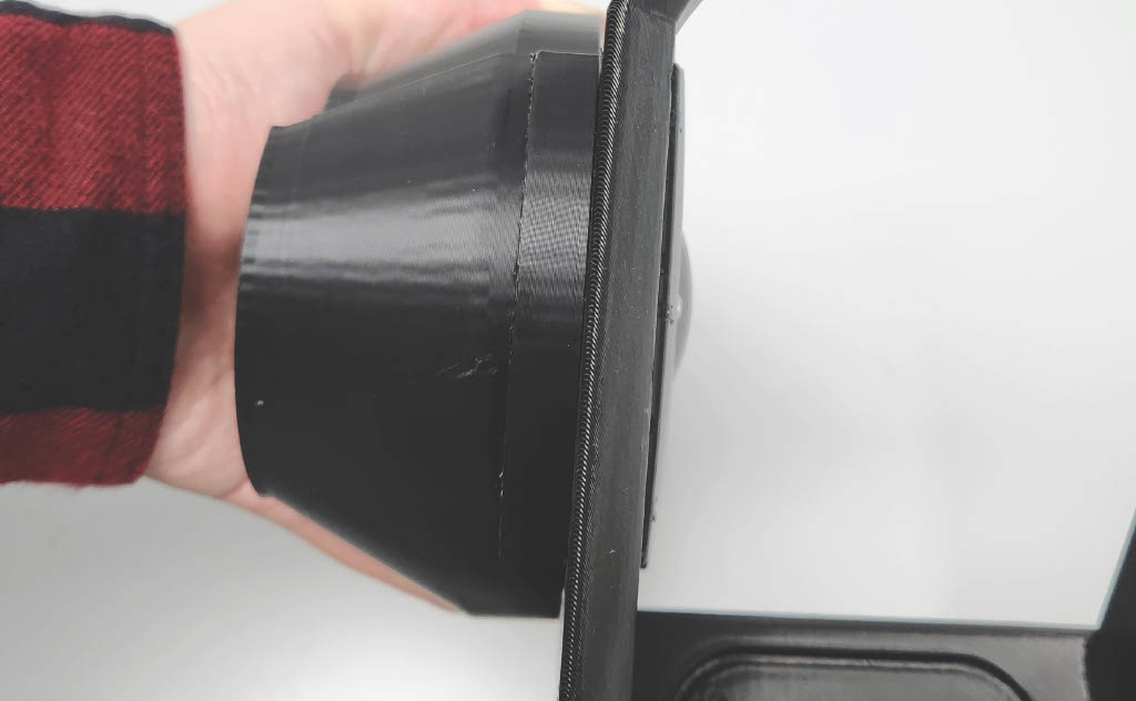
Step 15 — Check Assembly
Check that there are no gaps between modules.
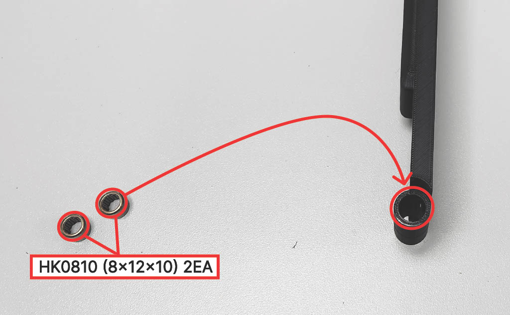
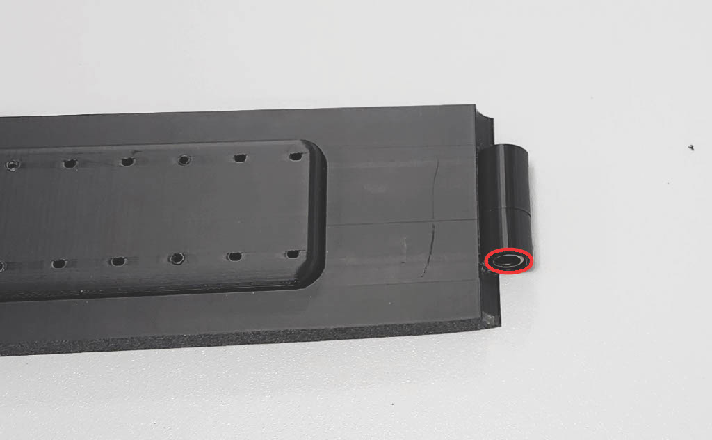
Step 16 — Passive Hinge Bearings
Insert two (2) HK0810 (8×12×10) into the holes in the Passive Hinge section of the Shank Structure.
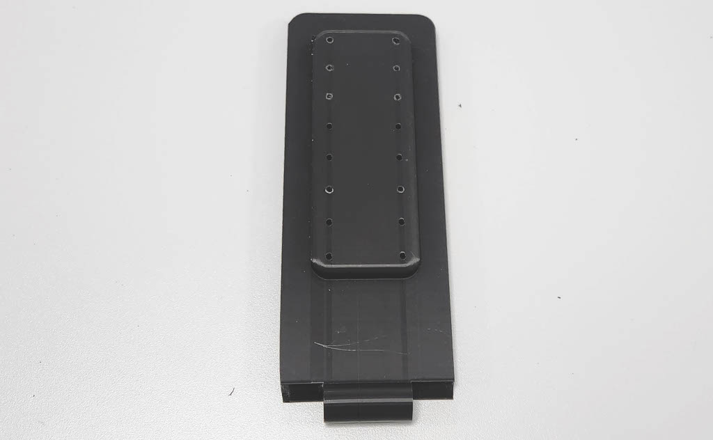
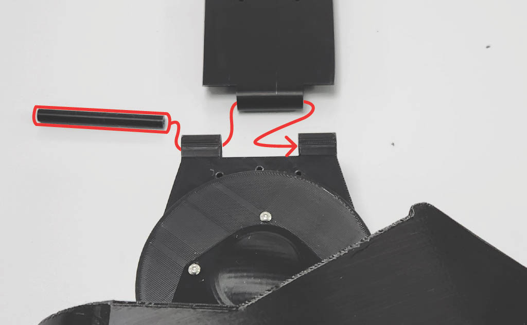
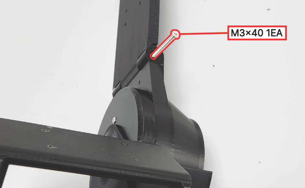
Step 17 — Shank Structure & Hinge Pin
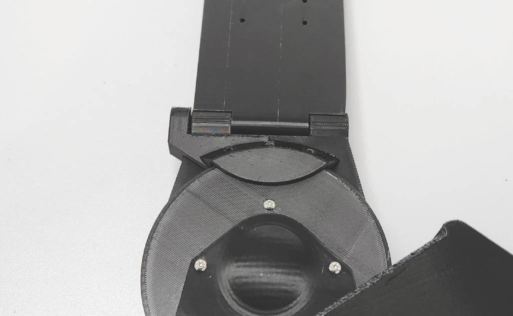
Fit the Shank Structure to the Ring Gear. Insert the Hinge Pin, then fasten using one (1) M3 × 40 mm screw. Tighten fully.
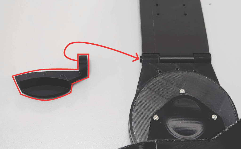
Step 18 — Upper Bracket to Hinge Pin
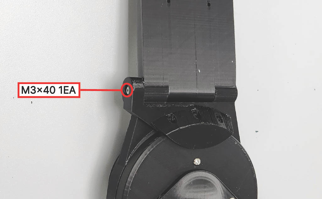
Fasten the Upper Bracket to the Hinge Pin using one (1) M3 × 40 mm screw. Tighten fully.
Step 19 — Upper Bracket to Ring Gear
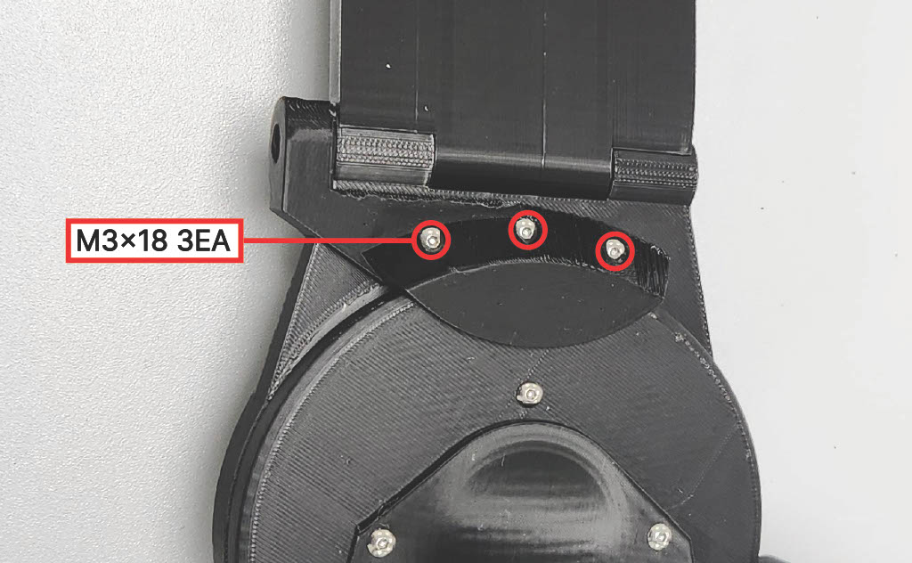
Fasten the Upper Bracket to the Ring Gear using three (3) M3 × 22 mm screws. Tighten fully.
Step 20 — Calf Compression Sleeve & Strap Anchor
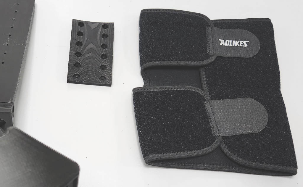
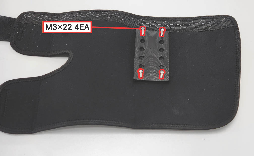
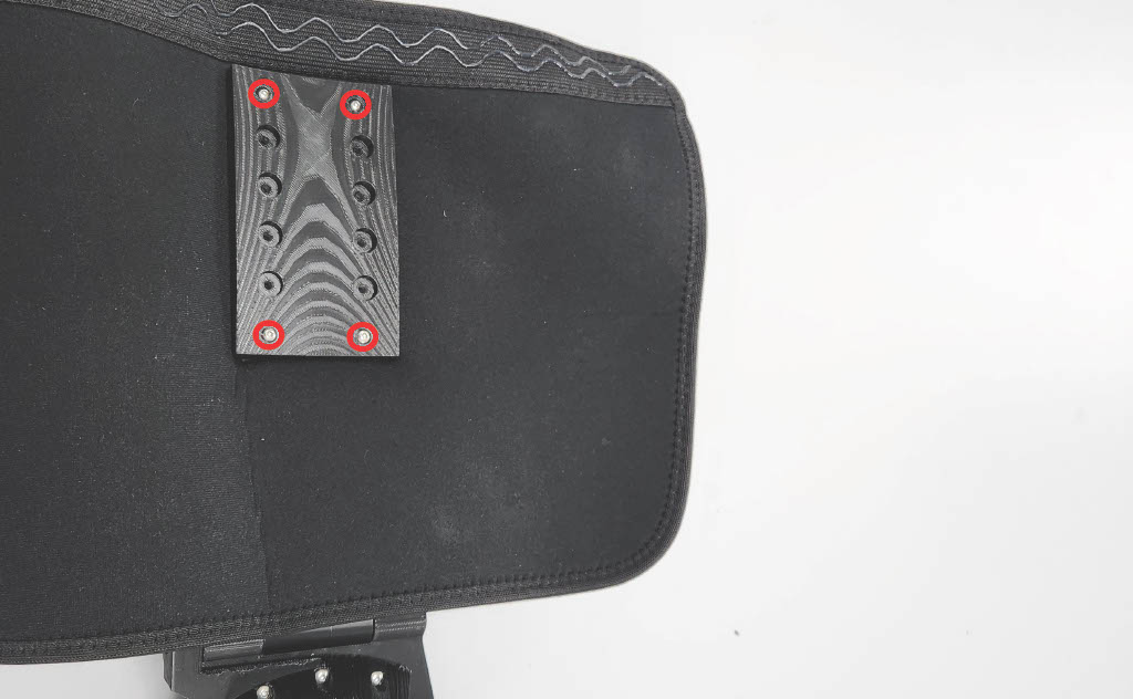
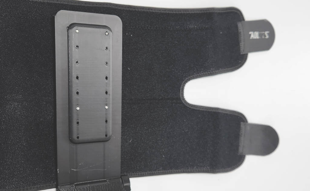
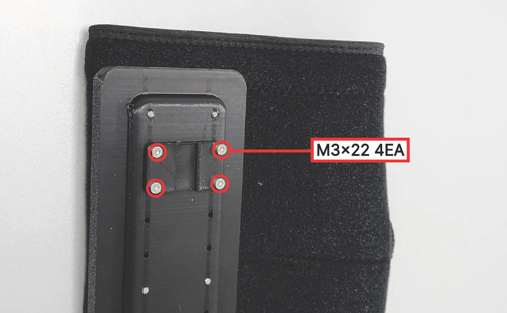
Fasten the Calf Compression Sleeve and Strap Anchor to the Shank Structure using four (4) M3 × 22 mm screws. Tighten fully.
⚠️ Caution: Select the size option based on the user's shank length, then fasten through the corresponding holes.
Step 21 — Wire Guide
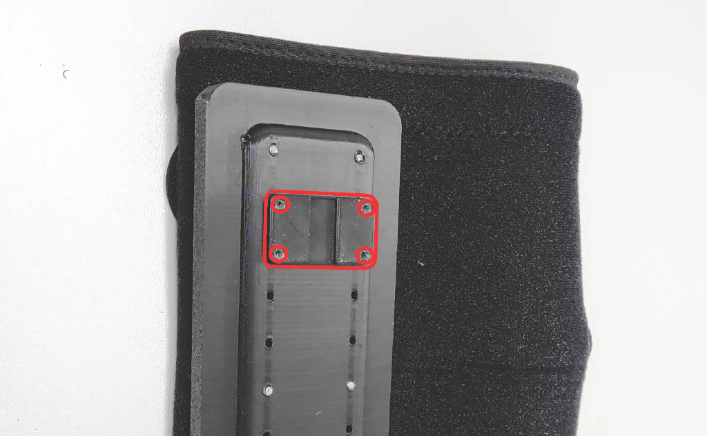
Fasten the Wire Guide using four (4) M3 × 22 mm screws. Tighten fully.
Step 22 — Dorsal Interface
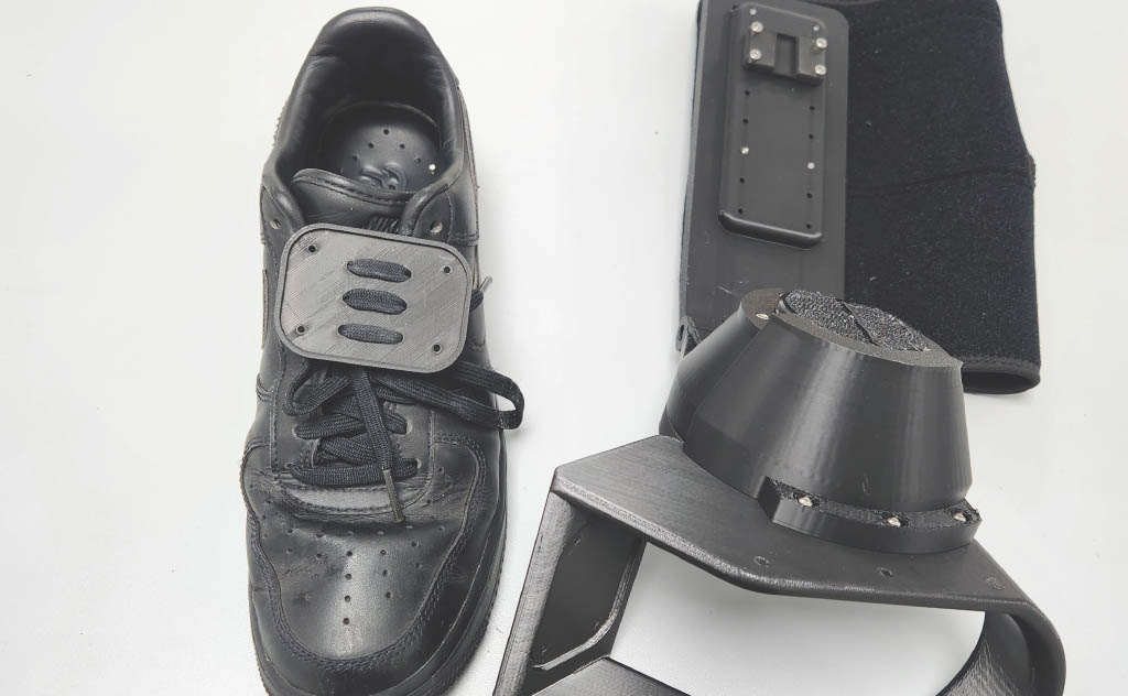
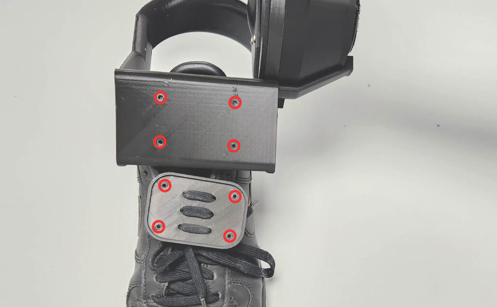
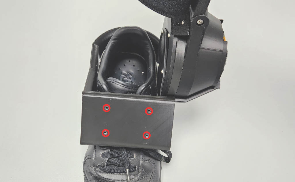
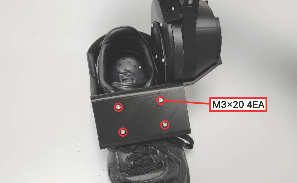
Fasten the shoe-mounted Dorsal Interface to the Carrier using four (4) M3 × 20 mm screws. Tighten fully.
ℹ️ Note:
This step attaches the dorsal interface to the device.
Instructions for mounting the dorsal interface onto the shoe are provided in the
Shoelace Fixation Guide.
Step 23 — Auxiliary Lace
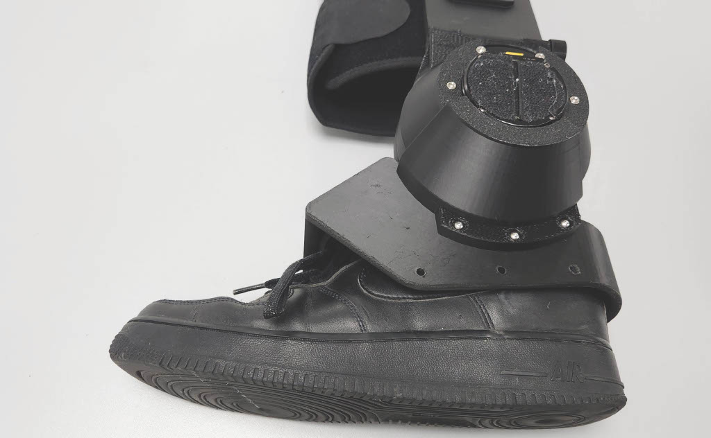
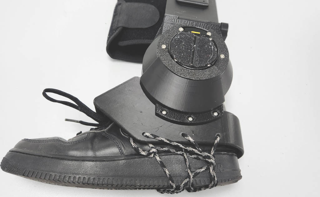
Use the Auxiliary Lace to secure the Dorsal Interface and Carrier assembly to the shoe.
ℹ️ Note:
Detailed lace routing and tying instructions are provided in the
Shoelace Fixation Guide.
Step 24 — Complete 🎉
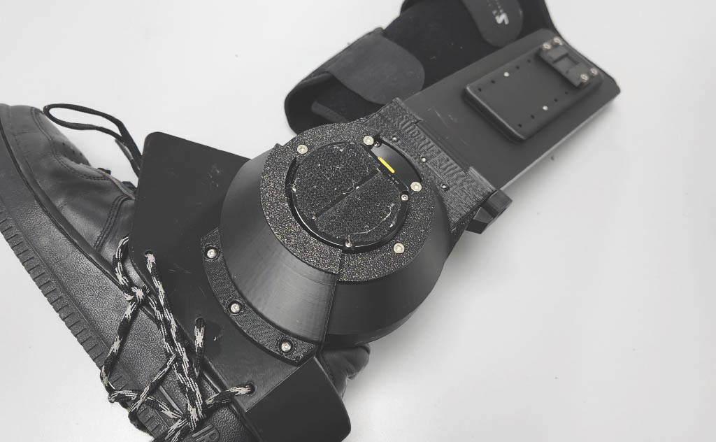
Assembly complete.
5. Alignment & Fit Verification
After assembly, perform the following checks:
Mechanical Checks
| Check | Expected Result |
|---|---|
| Gearbox rotation | Smooth, no grinding or binding |
| Hinge movement | Free inversion/eversion motion |
| Motor operation | Spins without obstruction |
| Shoe interface rigidity | No wobble at mounting point |
Fit Checks
- [ ] Shank aligned with lateral side of lower leg
- [ ] Ankle joint axis approximately aligned with device axis
- [ ] Calf sleeve secure while comfortable
- [ ] Laces tensioned evenly across dorsal interface
- [ ] No pinch points during range of motion test
6. Safety Notes
- Do not over-tighten M3 bolts — PLA can crack under excessive torque
- Inspect all structural joints before human testing
- Check for pinch points around hinge and gearbox